
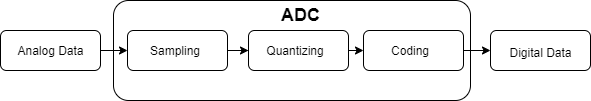
An ADC (analog to digital converter) is an electronic circuit that converts the analog data (continuous) from nature into digital data (binary). The ADC circuits can be found as a stand-alone ADC IC module or embedded into microcontrollers. The following features are best for you to understand before you go deeper about ADC.
ADC Features
1. Reference Voltage
It is a voltage required to act as the reference in calculating the digital data. The formula can be described as the following:
ADC digital data = (Vin/Vref) x Max of digital data
While Vin is the analog data from nature (measured by a sensor), Vref is the reference voltage, and Max of digital data is the maximum number of digital data in the coding process.
2. Sampling Rate
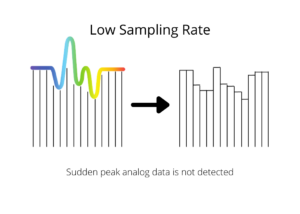
It defines the conversion speed of analog to digital the ADC can do every second. The unit to show the sampling rate is SPS (sample per second). To get the information on the sampling rate, one must check the related datasheet.
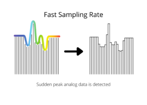
A high sampling rate helps you to pick sudden peak data properly, while the lower one is not able. This is the benefit of a fast sampling rate.
3. Resolution
It determines the accuracy level of the ADC. An 8-bit resolution ADC has different accuracy from a 12-bit resolution ADC. The input voltage for an 8-bit ADC can be converted into 255 digital values which are the result of 2n−1. On the other hand, a 12-bit ADC will convert its input voltage into 4095 digital values. To sum it up, the 12-bit ADC has higher accuracy than the 8-bit ADC. The higher the resolution is, the higher the accuracy is.
For example:
Suppose you have an ADC IC module with 8-bit resolution and 5vdc as Vref. That 8-bit means 255 combinations of digital values. It’s taken from this formula.
2n−1 = Amount of Combinations
28− 1 = 255
The actual ADC steps (bits) are 256 because it starts from zero (0-255).
The “0” represents 0000 0000 the least value, while the “255” represents 1111 1111 the most value.
To calculate the voltage changes, keep in mind the Vref is 5Vdc.
Voltage changes = Vref ÷ total ADC steps
= 5V ÷ 256
= 19.5 mV / bit
It means that the 8-bit resolution ADC module will change the voltage of 19.5 mV for every step. To get a higher resolution, then you need to get more n-bit. Let us try with 10-bit then
210 − 1 = 1023
The actual bits are 1024 (0-1023). Then the voltage changes will be.
Voltage changes = Vref ÷ total ADC steps
= 5V ÷ 1024
= 4.88 mV / bit
If your application needs voltage changes under 4.88mV, then you must go for another higher resolution ADC module.
Working Principle of ADC
The ADC consists of the following sub-process in converting analog data to digital data. Take a look at the illustration below.
In this case, let’s assume we are using a 4-bit ADC resolution.
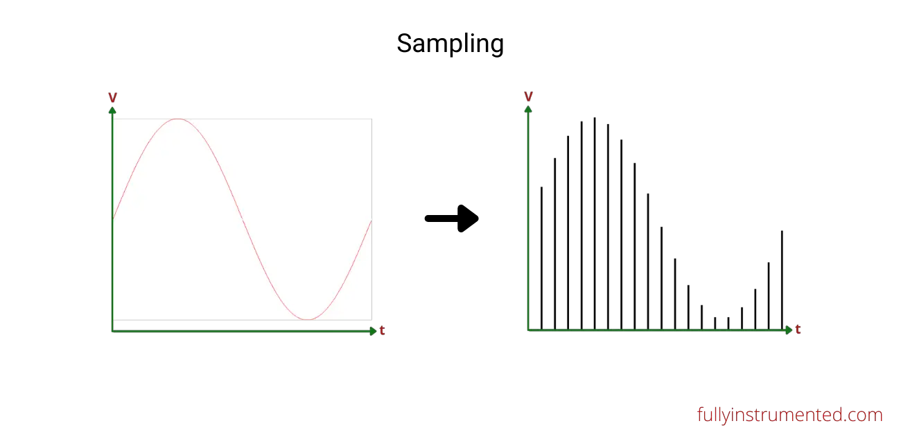
1. Sampling
It is described as the process to take a certain value of the analog data at a certain time point in the same period. The higher the sampling frequency, the more data obtained, then the fast the conversion rate is.
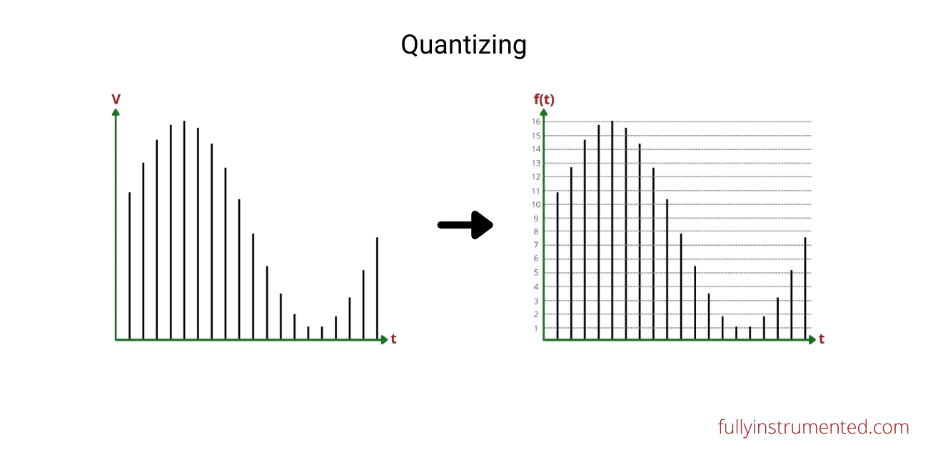
2. Quantizing
It is to group certain values data obtained from the previous process into data groups. The higher the data group number, the lesser the certain values data gap obtained from analog data, then the higher the accuracy is.
3. Encoding
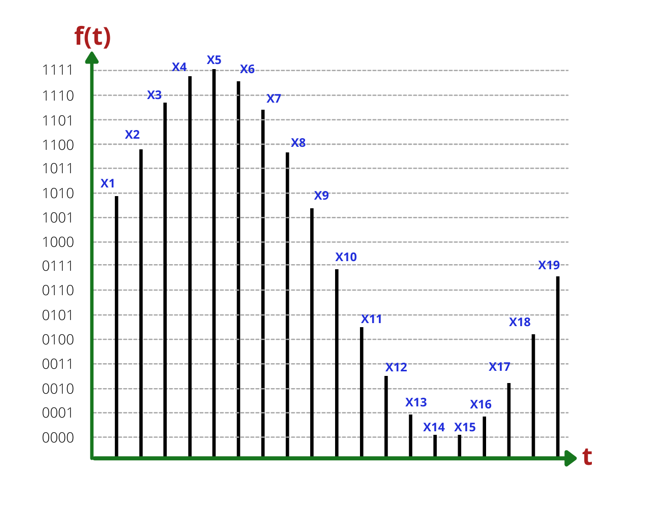
This process is to code the data of quantizing to digital (binary) form. Since we use a 4-bit ADC resolution, then the result is as the following.
X1 = 1010, X2 = 1100, X3 = 1110, X4 = 1111, X5 = 1111, X6 = 1111, X7 = 1110, X8 = 1100, X9 = 1010, X10 = 0111, X11 = 0101, X12 = 0011, X13 = 0001, X14 = 0001, X15 = 0001, X16 = 0001, X17 = 0011, X18 = 0101, and X19 = 0111.
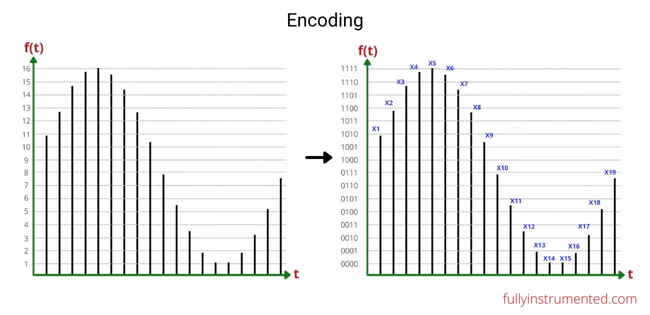
To get a larger view of the encoding graphic, look at the following picture.
Here is another great presentation for 2, 3, and 4-bit.
ADC Types
1. Flash ADC
This type of ADC consists of comparator series. The input signal is connected to non-inverting pins. At the same time, the inverting pins are connected to the voltage divider ladder. It is the simplest ADC type. The working principle is pretty simple. When the input signal (voltage) is above of certain ladder level, then all the bits of output below it will be set to “one”. The final binary reading is obtained through the table of comparator outputs and translator(encoder) outputs relation.
2. Counter Ramp ADC
This ADC type needs a longer time to get the binary output. It consists of the binary counter, the comparator, the digital to analog converter, the control circuit, the AND gate, and the latches. It is also known as digital ramp ADC. The higher the resolution is, the longer the conversion time is. It is based on the formula as below:
Tc(max) = (2n − 1) Tclk
The conversion starts at the same time as the binary counter. The RESET condition will be applied when the comparator yields “zero” and indicates that the binary output will be obtained.
3. Successive Approximation Register ADC
It consists of the comparator, the digital to analog converter, the successive approximation register, and the control circuit. The conversion starts by comparing the input voltage (Vin) and the DAC voltage (Vdac). The MSB (most significant bit) will be set by “one” and the rests will be “zeroes” at the beginning of the cycle. When Vin > Vdac then the next bit after the MSB will be changed to “one”. If the Vin < Vdac then the next bit will be changed to ”zero”. The conversion time it takes equals the following formula:
Tc = N × Tclk
This ADC provides good accuracy and requires low power consumption.
Real-Life Application
As stated in the previous section, the ADC in real life can be found in a stand-alone ADC IC module or embedded into microcontrollers. The truth is, however, you can actually build any type of your own ADC according to your need and desire from scratch. In the case you are in dire need and short time, then it is not wrong to use the ADC module or ADC in the microcontrollers.
1. Stand-alone ADC IC module (ADS1115)
The ADS1115 module here is the sample product of the stand-alone ADC IC module. It has a 16-bit resolution that makes it high precision for the conversion. There are four channels available which make it sufficient when you have more than one analog sensor. Its sample rate is 3300 samples per second. It supports the I2C interface to communicate with any single-board computers through SCL and SDA pins.
It is definitely worth it and compatible with single-board computers (SBC) that do not come with the analog or ADC GPIO. To connect the ADS1115 to Raspberry Pi, as the SBC example, it is important for you to know how the I2C bus connection works between the two.
Datasheet: https://www.ti.com/lit/ds/symlink/ads1115.pdf
2. ADC in A Microcontroller (ATMega8)
This section takes ATMega8 as the sample product in which the ADC features exist. It features a 10-bit successive approximation ADC. This IC provides 6-channels ADC pins through the SPI serial port.
This kind of product has a different purpose than a stand-alone ADC IC module indeed. It holds more functionality aside from the ADC features. A microcontroller can process the analog-to-digital data conversion until show the reading in the LCD display.
3. ADC in Arduino Nano
When it comes to ADC in Arduino, that simply means ADC in ATMega microcontroller products.
As you may know, there are several Arduino board models out there. In this case, we only cover Arduino Nano V2.3. It is a board based on ATmega168. To use the ADC feature, you need to pay good attention to pin 18 as the AREF (ADC voltage reference) and pins 19-26 as the analog inputs (Vin). It provides a 10-bit resolution ADC.
This kind of product has more purpose than a stand-alone ADC IC module indeed. It holds more functionality aside from the ADC features. A microcontroller can process the analog-to-digital data conversion until show the reading in the LCD display.
Datasheet: https://www.arduino.cc/en/uploads/Main/ArduinoNanoManual23.pdf
Measuring Instruments with ADC
There are countless measuring instruments with ADC. The analog data, commonly in volt, is translated into digital data (binary) by using ADC. Digital oscilloscope (not the analog one) is one of the examples. Aside from that, a multimeter is the easiest one to understand and most commonly used in the electronic world.
Conclusion
The convenience we are experiencing in this modern era is not free from a complex system. For example, we can easily check the temperature of certain things such as the room or refrigerator. There are various mechanisms working behind it. Temperature is analog data provided by nature. On the other hand, the temperature reading shown at a display of electronic equipment is the result of digital data processing. That includes the help of the ADC (analog to digital converter).