
Ever wonder how an oscilloscope works? Want to learn how this electronic testing instrument measures and then processes the readings to be displayed on the screen for us to see? We cover both them here.
How Analog Oscilloscope Works
Analog oscilloscope or more commonly known as the ‘Cathode ray oscilloscope (CRO)’ is the predecessor of the now more commonly used ‘Digital storage oscilloscope (DSO)’. Unlike a DSO that is made using semiconductor ICs and a digital colored display, an analog oscilloscope consist of 2 cathode ray tubes which display the signal waveform on its screen.
The function of Cathode-Ray Tubes
The cathode ray functions as a beam of electrons that is accelerated onto the fluorescent screen by the heated cathode tubes, this entire setup is also known as an electron gun. Its function is to generate the electron beam and adjust its intensity and focus. In an Analog oscilloscope, cathode ray tube with electrostatic deflection is required to be able to measure high frequency signals.
Working
Just like in a digital oscilloscope, there are multiple stages to producing a signal on an analog oscilloscope’s display.
- Heating filament: The heating filament or lamp is placed at the very end of the enclosure of the scope so that it can heat up the cathode that will then emit electrons forming an electron beam.
- The Control grid: The ‘Electron beam’ emitted by the cathode is then passed through the ‘Control grid’ to help the user control the brightness of the trace. This procedure is also known as Intensity control.
- Focus electrode: The ‘Focus electrode’ is cylindrical in shape so that beam of electron can pass through it. The purpose of this electrode is to focus the beam of electron on the path.
- Deflection plates: There are a total of 4 deflection plates, 2 vertical and 2 horizontal. In some oscilloscopes there are two deflection plates. These plates are also known as vertical and horizontal plates, and their purpose is to deflect the beam according to the input. It can be deflected horizontally (left to right) as well as vertically (up and down).
- Anode: The Anode is connected to a high voltage which is used to accelerate the electrons to the screen.
- Screen: The screen is made of glass material that has a layer of fluorescent inside it, which is then lit up by the accelerated electrons.
- Input signal & Amplification: The input signal from the probe is then amplified with the help of an amplifier circuit within the scope, and the signal is then sent to the vertical deflecting plate to be presenting on the screen.
Controls of An Analog Scope
Since analog oscilloscopes are considered to be obsolete, comparing them in terms of ease of use with a more recent Digital storage scope (DSO) would be a clear win for the latter. Although most controls are pretty much similar such as time base settings, trigger controls, AC, DC & GND controls, there are some controls that require calibration.
- Focus Control: Focus control is no longer required in today’s DSOs, although it was an important feature in its predecessor, the cathode ray oscilloscope. Its basic purpose is to allow the user to control the focus electrode allowing for a clear trace
- Intensity control: As the name suggests, it controls the intensity or the brightness of the trace being outputted on the screen by controlling the cathode voltage. In recent digital oscilloscopes such settings are not required as the display is digital.
- Sensitivity: Allows the user to control the amplification of the input signal to the oscilloscope. For weak signal higher sensitivity settings for be required.
- Beam finder: Allows the user to find the trace on the screen when it’s not visible
- Graticule: The ‘Graticule’ is the grid on the screen of the oscilloscope that allows the user to measure the amplitude and the time-base manually by counting. Normally each box in the grid is approximately 2mm wide, and such a grid is only available in Analog oscilloscopes. In modern scopes, thanks to digital screens, a digital grid is already made on the screen which the users can use to automatically find out the amplitude and other parameters without the need for manually counting each box.
How Digital Oscilloscope Works
Since most of the analog oscilloscopes are obsolete by the manufacturers, this article will only be focusing on the working of a Digital Storage Oscilloscope (DSO) as they are more widely used and available.
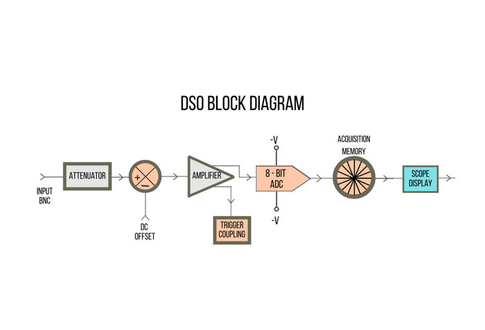
An oscilloscope has five major blocks that define its functioning and they are Probing, Amplification, Analog to Digital conversion, Time Base & Memory acquisition, and Display.
Stage 1: Probing
To measure the reading or to analyze an electronic signal, probing the circuit with the provided probe(s) is the first step. The probe is placed on the point of interest and the ground clip is connected to the ground or the lower potential point. The reading between the two points (point of interest and ground) is then sensed by the probe and is sent to the oscilloscope for further processing.
A probe also has a 1× or a 10× feature, allowing the users to choose between the levels of sensitivity. The 1× configuration allows users to measure signals with low amplitudes in a low impedance circuit while a 10× configuration allows you to measure circuits with higher input impedance.
Stage 2: Amplification
The next stage is where the input signal measured by the probe goes for analog signal conditioning.
This conditioning process consists of three stages, all of which are completed in order to accurately scale the waveform to be within the dynamic range of the analog-to-digital converter (ADC) and the amplifier. This process uses the parameters of V/div and offset, which in turn are determined by whether you are sensing a low-level or high-level signal.
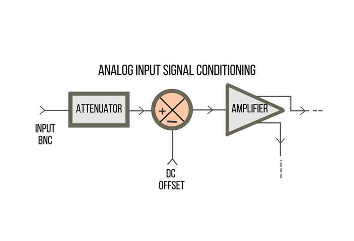
The signal is first scaled in the attenuator block. This block is made up of a network of resistor dividers.
When a high-level input signal is used, the signal is attenuated or lowered. But if you enter a low-level signal, it will be transmitted through to the next phase without being attenuated.
You may frequently input a signal with a DC offset, but you want to be able to display that signal at 0 V in the middle of the screen. To do this, an internal DC offset of the opposite polarity is applied to the signal to change the scale. This will place it in the center of the screen.
Finally, the signal enters the variable gain amplifier.
Depending on your V/div setting, this type of amplifier will either boost or lower the gain of your signal. So, whether you’re looking at a low or high-level signal, the answer is the same.
All in all……
If you’re working with a low-level signal, you’re probably at a low V/div setting, which tells the amplifier that the gain should be increased so that you can use the entire range of the ADC.
On the other hand, if you’re working with a high-level signal, it will have been attenuated in the first stage of this procedure, and the amplifier may further attenuate the signal in this stage by decreasing the gain, again to scale the signal inside the dynamic range of the ADC.
Stage 3: Analog to Digital Conversion (ADC)
With the signal conditioned to be aligned with the dynamic range of the analog to digital converter, the analog to digital conversion can begin.
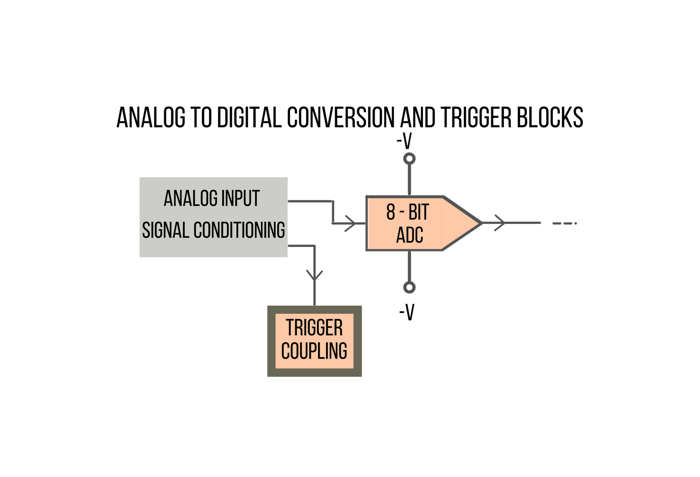
The ADC block is the foundation of all DSOs (Digital Storage Oscilloscopes).
The analog input signal is transformed into a series of digital words at this point.
The majority of today’s DSOs use 8-bit ADCs, which enable 256 distinct digital output levels/codes. These digital binary codes are saved in the oscilloscope’s acquisition memory, which will be covered in more detail later.
The scope (oscilloscope) will attempt to utilize the whole dynamic range of the ADC in order to achieve the greatest resolution and most accurate data.
While the data is being converted in the ADC, the scope is evaluating the trigger conditions required to establish a unique point in time on the input signal for timed acquisition. The trigger comparator block will emit a non-inverted waveform with a duty cycle that is based on what you set the trigger level to on the oscilloscope.
The trigger logic block will then either invert the waveform before letting it pass through, or it will allow the non-inverted waveform to pass through to the next step, depending on what you set the trigger type to. This trigger signal is subsequently used as the unique synchronization point in time in the time base block in the following step.
Stage 4: Time Base & Memory Acquisition
The timebase block governs when ADC sampling begins and ends in relation to the trigger event determined in the preceding step.
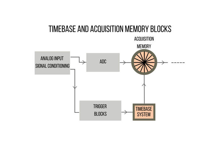
Furthermore, the timebase block regulates the ADC’s sample rate based on the scope’s available acquisition memory depth and timebase setting.
When the Run key is hit, the timebase block allows the digitized data to be continuously stored in the scope’s circular acquisition memory at the proper sample rate.
While the timebase block advances the addressing of the circular acquisition memory buffer after each sample, it also counts the number of samples taken up to a particular amount that is depending on the oscilloscope’s memory depth and trigger location.
When the timebase block detects that the minimal number of samples of your signal has been gathered, it enables triggering and begins looking for the first qualifying point of the output trigger comparator.
After detecting the trigger event, the timebase block begins collecting the needed amount of samples.
When all of the samples have been saved, the timebase block shuts sampling and the operation proceeds to the next stage.
Stage 5: Displaying
The signal has now entered the final stage. After all of the samples have been acquired, the data in the acquisition memory is backed out in a last-in-first-out sequence.
The signal is rebuilt from the samples, and the data is stored in the oscilloscope’s pixel display memory before being presented on the screen.
After the signal has been presented, it can then further be analyzed by the user for signal manipulation such as performing mathematical tasks or looking at the transient response of a circuit.