
Tolerance and allowance may be frequently understood as the same thing for some people. This is not weird because these two terms have a great relation in defining the limits of a dimension.
Basically, tolerance and allowance are used to describe the limits of an object dimension so that the dimension is acceptable for mechanical parts and machine parts to function efficiently.
However, either tolerance or allowance is pointed to a different object. Tolerance is the object dimension limit that will insert into, while the allowance is the object dimension limit that will be inserted.
It also can be explained as the tolerance is for the parts that will insert into a hole. Meanwhile, the allowance is for the parts that have that hole. Later on, both of them create an assembly.
Tolerance
A. What is Tolerance?
Mass fabrication or production of machine parts, such as shafts, studs, pulleys, gears, etc., cannot be manufactured with the exactly same dimension as the other. However, it can be precise to a certain allowable limit of dimensions, maybe in a maximum or minimum condition. This allowable difference between the limits of the dimension of a manufactured part is called tolerance.
B. The Purpose of Tolerance for Part and Component Manufacturing
The purpose of having engineering tolerance on a dimension of parts is to allow permissible variation and to limit dimension caused by inevitable errors from man, machine, material, method, measurement, and environment without affecting the overall performance of the final product.
The following are the common reason for assigning tolerance on the dimensions of mass-produced parts and components.
– Error
Inevitable errors from man, machine, material, method, measurement, and environment affect the ideal nominal dimension requirement of a manufactured part and product. The main point of this is that a certain part cannot be manufactured to perfectly to the desired dimension.
– Cost
Cost consideration of manufactured parts wherein higher tolerance requirements mean higher manufacturing cost and higher price of produced products results in consideration of allowable tolerance without affecting the function of the parts.
– Proper Function
Due to the need to manufacture higher precision parts and machines, limiting the dimension’s tolerance is necessary for a product to function properly.
A single part is designed with a basic size. Since there are errors that will contribute to the accuracy of dimension during parts production, the basic size is associated with tolerance where the limits of deviations are assigned – the upper limit and lower limit. For example, the length of a component is 25mm, the maximum deviation of this nominal dimension is allowed up to +0.1mm only and the minimum deviation is allowed up to −0.2mm. The value of tolerance of this basic size is the difference between the upper limit and lower limit or the difference between the maximum allowable size and the minimum allowable size. The actual size of conforming parts should lie between the set dimensional limit.
The dimension of parts at a maximum level is its maximum limit, and the minimum level is its minimum limit.
C. Drawing Examples of Tolerance
Below are examples of a parts drawing showing the tolerance of parts and how to calculate and measure the tolerance of parts.
Drawing 1
A shaft with a dimension of Ø12mm basic size with a tolerance of −0.038mm upper limit and −0.020mm lower limit.
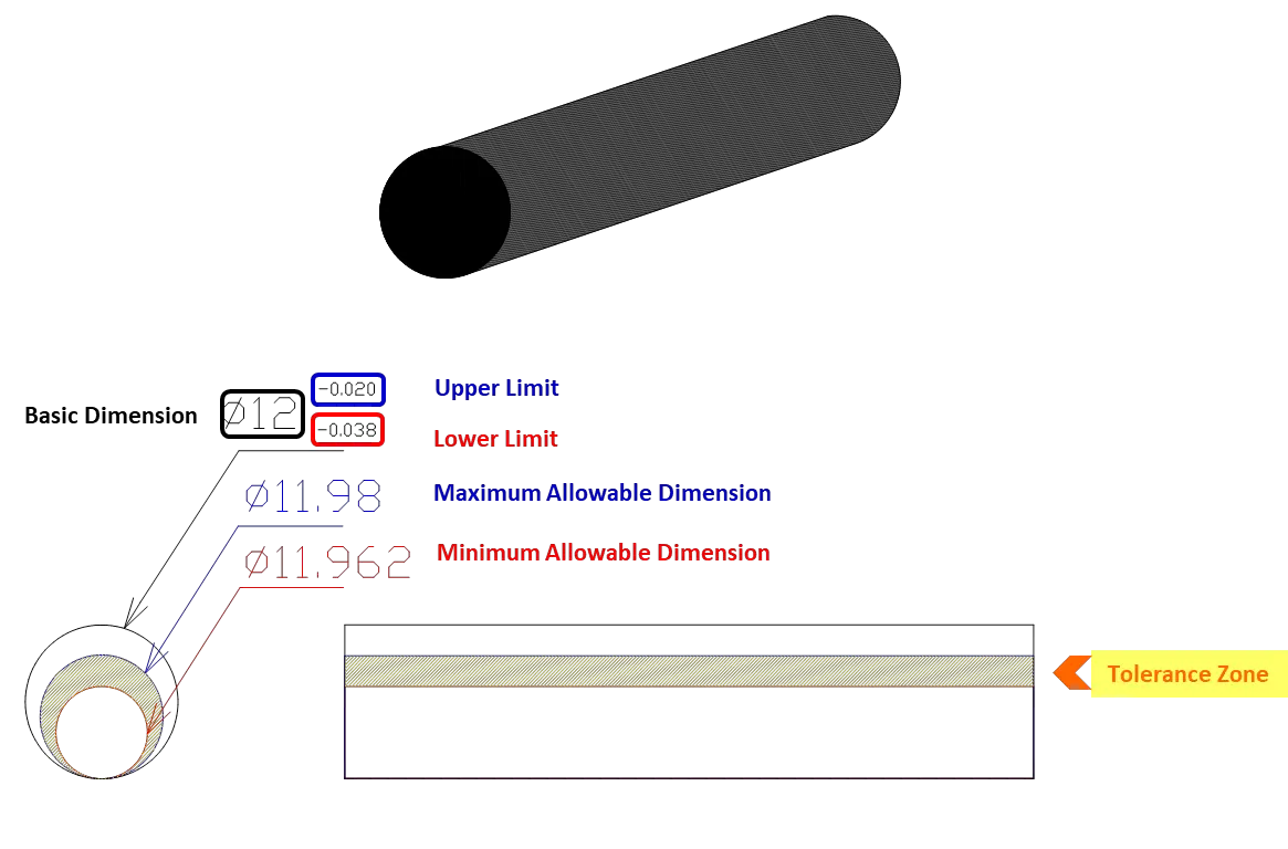
The maximum limit of the dimension of the shaft is Ø11.98mm and the minimum limit of the dimension of the shaft is Ø11.962mm.
The tolerance of the shaft can be obtained by getting the difference between the standard allowable minimum size and the standard allowable maximum size of the shaft.
To measure the actual dimension of shaft, a micrometer can be used.
![]()
Therefore the tolerance of the shaft must be 0.018mm only.
Drawing 2
A spherical symmetrical roller with an inside hole dimension of Ø12 basic size with a tolerance of +0.04 mm upper limit and 0 mm lower limit.
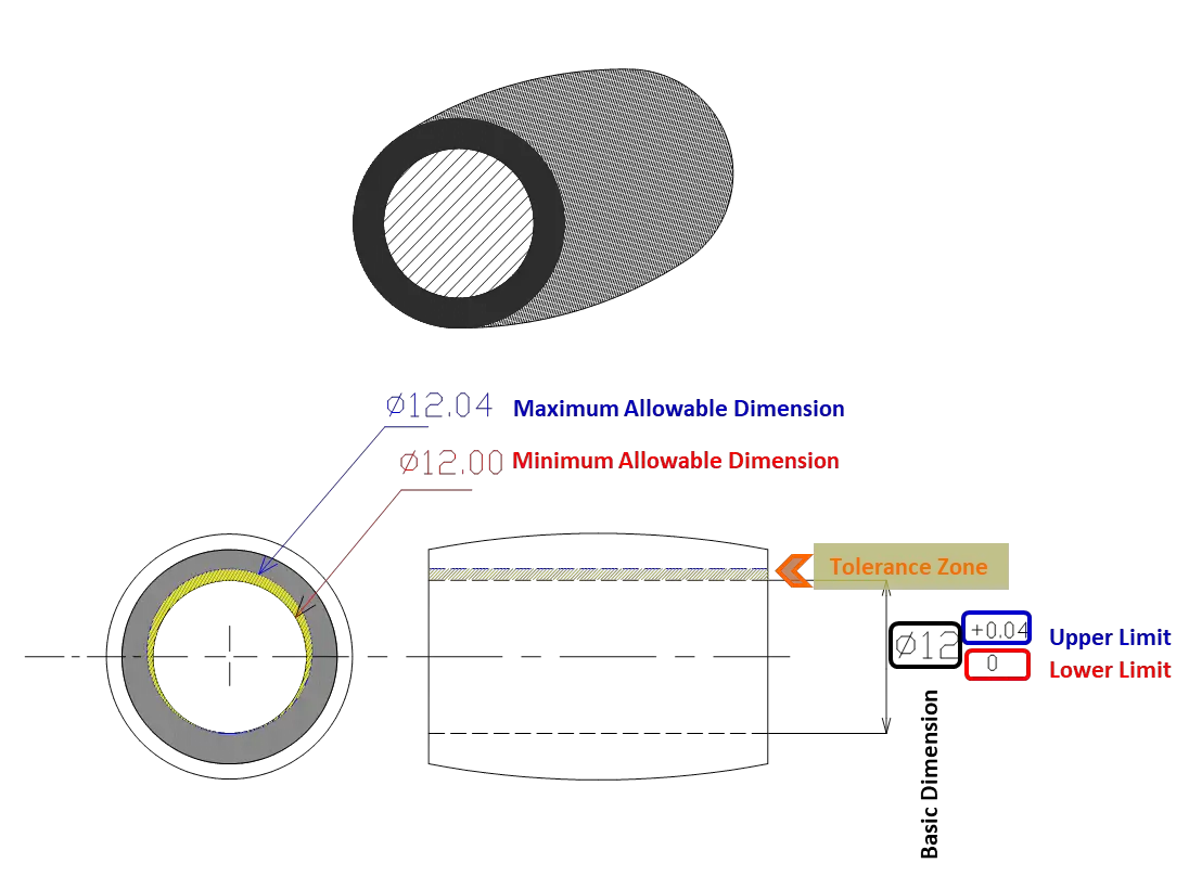
The maximum limit of the dimension of gear is 12.04mm and the minimum limit of the dimension of gear is 12.00mm.
The tolerance of the roller can be obtained by getting the difference between the standard allowable minimum size and the standard allowable maximum size of the roller.
To measure the actual dimension of the hole of the roller, a pin gauge can be used as a Go-NoGo gauge.
![]()
Therefore the tolerance of the roller must be 0.04mm only.
Drawing 3
A metal bracket with a dimension of 18 mm with a tolerance of +0.3mm upper limit and −0.2mm lower limit.
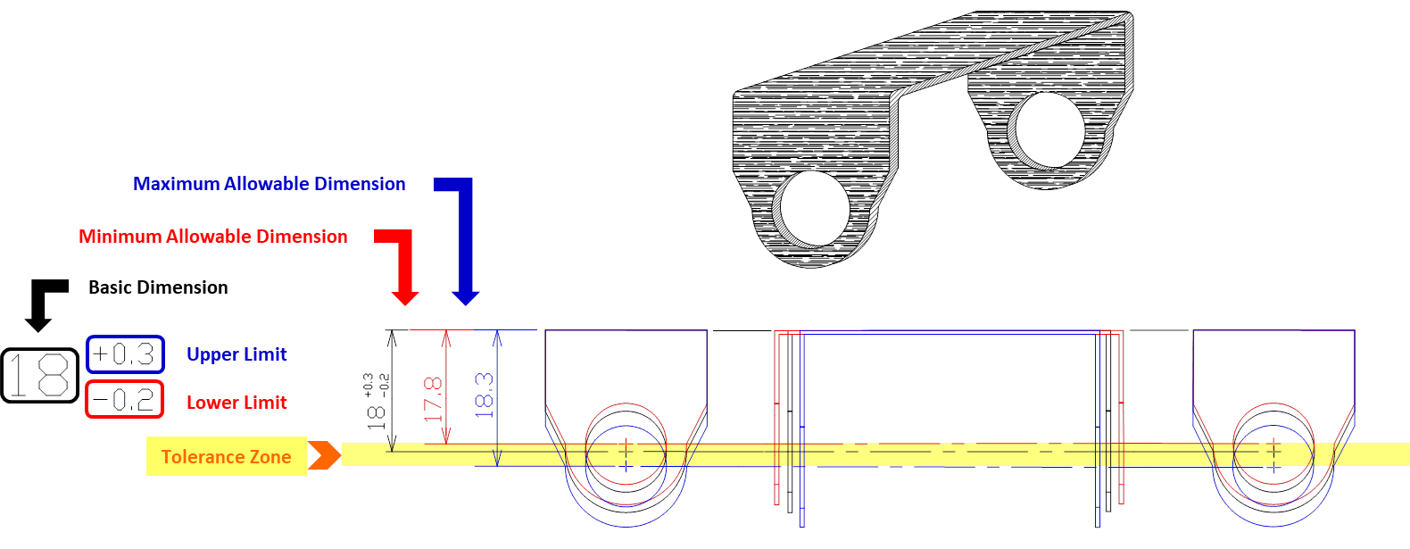
The maximum dimension is 18.3mm and the minimum dimension is 17.8mm.
The tolerance can be obtained by getting the difference between the standard allowable minimum size and the standard allowable maximum size of the metal bracket.
To measure the actual dimension of the metal bracket, a height gauge can be used as a measuring instrument.
![]()
Therefore the tolerance of the metal bracket must be 0.5mm only.
D. Types of Tolerance
There are mainly 2 systems of specifying tolerance: unilateral tolerance and bilateral tolerance.
a. Unilateral Tolerance
When the tolerance of the dimension lies in the same direction or in one side such as from 0 to positive values from 0 to negative values, this tolerance is unilateral. It is applied to parts whose function needs to be controlled purposely on one side.
Drawings 1 and 2 shown above are examples of unilateral tolerance.
Examples:
- 100 +0.05/0
- 90 +0.10/+0.05
- 100 0/−0.10
- 90 −0.05/−0.10
b. Bilateral Tolerance
Bilateral tolerance refers to the tolerance of dimensions where it can be either in both directions of the basic size as shown on drawing no.3 above. The lower limit of this tolerance is in negative value and the upper limit of this tolerance is in positive value.
This type of tolerance is applied to parts that do not require contacts on surfaces of parts during assembly.
Examples:
- 50 ± 0.5
- 25 +0.3/−0.1
Allowance
A. What is Allowance?
Allowance is a planned deviation set between mating parts and components. It is an intentional difference that must be kept between the two different parts or components that will be assembled. It can either be a positive allowance called clearance or a negative allowance called interference.
Allowance can be best described by the relationship between the shaft that will be inserted into a hole.
The degree of intentional difference between the assembled parts or allowance will result in a standard looseness or tightness needed to perform a certain function which refers to “fits”.
B. Types of Fit
There are 3 classifications of fits: clearance fit, interference fit, and transition fit.
a. Clearance Fit
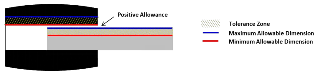
From the shown illustration, the space between the hole and the shaft means there is a clearance between these two parts. When the assembly of parts requires clearance between these two parts, this fit is called a clearance fit. Considering the hole size and the shaft size, clearance fit can be obtained by considering the minimum hole size and the maximum shaft diameter. The minimum hole size should be greater than the maximum diameter of the shaft. To determine the actual allowance of two parts with clearance fit, subtract the actual size of the diameter of the shaft to the actual hole diameter which should always result in a positive nominal value that’s why it is called a positive allowance. The minimum clearance and the maximum clearance is strictly controlled in this kind of fit, wherein, the minimum clearance
In this kind of fit, the shaft can be inserted into the hole smoothly without applying force. Parts can be slid onto each other and the shaft can be rotated. Parts may not easily wear in this kind of fit.
The common example of parts applying clearance fits is rotating parts such as wheel, axle and hinges used for doors and cabinets.
Classification of Clearance Fit
- Slide clearance fit – Small clearance is controlled in this kind of fit. It is intended for assembled parts that require slow motion. (Example: tailstock movement of a lathe, sealing rings).
- Running clearance fit – This kind of fit requires a bigger allowance than slide fit. It is intended for assembled parts that require moderate motion or rotation. (Example: lubricated bearings, shaft pulleys)
- Loose running clearance fit – This kind of fit is for assembled parts with fast motion or rotation. It has the loose control of allowance compared to slide and running fit since the effect of other factors such as temperature, dirt, dust contamination, and corrosion is considered in this kind of fit. Parts that are assembled in this kind of fit also have greater allowable tolerance.
b. Interference Fit
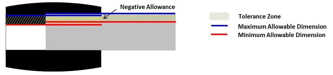
An interference fit is the opposite of a clearance fit. As shown in the illustration above, the shaft diameter is larger than the hole diameter, the fit requirement for this is interference fit. In an interference fit, a shaft cannot be inserted into a hole without applying force and needs secondary tools to attach the parts together. Either of the parts will wear after assembly and should be replaced during disassembly or repair.
In an interference fit, the maximum hole size should always be smaller than the minimum hole diameter of the shaft.
Common examples of interference fit parts are press-fitted bushing, pins, dowel pins, and fixed rings on a curtain.
Classification of Interference Fit
- Forced Fit – In this kind of fit heating and cooling is applied to obtain the desired fit.
- Driving Fit – This kind of fit is associated with purposely assembled parts that do not need to be disassembled. This kind of fit is obtained by high pressure using an industrial cold press or hot press process.
- Press Fit – In this kind of fit, this has lesser interference than driving fit so that the parts can be replaced during maintenance or disassembly of machines. It can be assembled by hand or by using a hammer.
c. Transition Fit
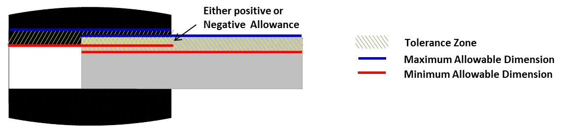
A transition fit is in between clearance fit and interference fit. It is based on the actual size of the assembled parts that may result in either clearance fit or interference fit depending on the tolerance zone of the involved parts.
Transition fit is used when the accurate location of the parts is necessary which is not controlled in a clearance fit and interference fit. In this kind of fit, assembly of parts does not need high pressure, and there’s no need to worry about encountering play between the assembled parts due to large clearance.
As shown below, the tolerance zones of the shaft and hole are overlapping.
Classification of Transition Fit
- Fixed fit – In this kind of fit, it has small clearance and negligible interference. Parts can be assembled and disassembled easily by light force using hand.
- Similar Fit – Similar fit has near to zero clearance and small interference. Parts can be assembled and disassembled by light force using a rubber mallet.
Summary of Comparison of Tolerance and Allowance
| Tolerance | Allowance |
| 1. Tolerance applies to a single part or component. | 1. Allowance applies to two mating parts, such as a shaft inserted into a hole. |
| 2. Tolerance is an unplanned deviation of a nominal dimension of parts/components in consideration of the errors that is inevitable during the manufacturing and production process. | 2. Allowance is a planned deviation between two parts to be assembled in order to meet the necessary fit. |
| 3. Tolerance involves allowable variation; the upper limit and lower limit of a basic dimension of parts or components. | 3. Allowance is an intentional difference involving the upper and lower limits of shafts and holes assembled together. |
| 4. Tolerance is the difference between the maximum allowable dimension and the minimum allowable dimension. | 4. Allowance is an assigned standard difference of the dimensions between two mating parts. |
| 5. Tolerance value is an absolute value. | 5. Allowance value can either be positive or negative. |
