
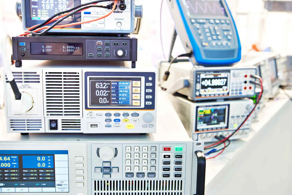
You are indeed about to use a multimeter, oscilloscope, clamp meter, capacitor tester, etc which are classified as electronic measuring instruments when your job is in regard to the electronic world.
Some of the electronic measuring instrument’s basic working principle is to send or create signals to stimulate and get the responses of electronic components or circuits under certain tests. By using this way, the measuring devices can detect the faults and malfunctioning. This one recalls us on how the oscilloscope, wire tracer, underground locator, etc work.
Measuring tools such as ohmmeter, capacitance tester, etc, are no need to stimulate signals. The operators only need to guide the probe to the object to be measured and get the reading results.
Whether for daily or even large-scale industries, talking about the list of electronic measuring tools is great to let us know how actually they are all. Here we cover 22 electronic measuring instruments that we commonly use in the electronic world.
| Name | Function |
| Multimeter | Measures voltage, current, and resistance |
| Ammeter | Measures current |
| Voltmeter | Measures voltage |
| Ohmmeter | Measures resistance |
| Clamp meter | Measures current |
| Function Generator | Generate electronic signals |
| LCR meter | Measures inductance, capacitance, and resistance |
| Capacitor Tester | Measures capacitance |
| ESR meter | Measures the equivalent series resistance |
| Oscilloscope | Displays graphically of voltage or current signals |
| Frequency counter | Measures frequency |
| Emf meter | Measures AC electromagnetic fields |
| Gaussmeter | Measures DC fields |
| Spectrum analyzer | Measures the input signal magnitude against frequency within the full frequency range |
| Logic analyzer | Displays and captures multiple signals of a digital circuit |
| Transistor tester | Test the electrical behavior of solid-state diodes and transistors |
| USB tester | Test the USB ports functionality and wiring |
| USB multimeter | Test USB port function, measure voltage and current |
| Wire tracer | Aid to locate the energized and de-energized wires, pipes, and cables |
| Continuity tester | Test the connectivity of a complete circuit |
| Test light | Determine the electricity presence |
| Network analyzer | Measures the network parameter of electrical networks |
List of 22 Electronic Measuring Instruments
The following table will tell you each function from the electronic measuring instruments you are about to read.
1. Multimeter
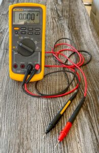
A multimeter is the most popular electronic measuring instrument which has some kinds of measurement functions included in one package. A common multimeter at least has the ability to measure current, voltage, and resistance. Based on the display, you could recognize that there are two types of multimeters available on the market. They are analog and digital. The analog type uses the needle as a moving pointer to display the measurement reading. In comparison, the digital type uses a digital display, which is mostly represented in LCD with seven segments of character type.
Aside from the display aspect, the analog type’s reading procedure requires more user steps to get the reading value. The user is required to do the calculations such as multiplication and division to get the actual reading. Meanwhile, the digital type immediately shows the reading without doing any manual math calculation.
Another feature that might exist in a multimeter is continuity testing. The user is only required to put the probe on the first end and another probe on another end. As the indicator, the buzzer will make a sound if the circuit is connected. Some multimeters also have a feature to test the transistor pins. People often mistake the pin position of transistor feet. The multimeter can help to identify which are the collector, base, or emitter pins.
2. Ammeter
An ammeter (amperemeter) is an electronic measuring instrument especially used to measure the current. To do the measurement, it is a mandatory thing to connect the instrument in series connection with the circuit where the current is going to be measured. Most ammeters have really low intrinsic resistance, so that the significant voltage drop would not occur in the circuit.
Based on measurement range, ammeter can be categorized as miliammeters, microammeters, or picoammeters. As the technology advances, the ammeter originally featured by the analog display is also developed with a digital display feature.
3. Voltmeter
As its name implies, the function this instrument has is to measure voltage exactly. Voltage is the difference of electric potential between two points in a circuit. In order to use the voltmeter, the user must connect the instrument and the two points to be measured in a parallel configuration. Typical voltmeters must have high intrinsic resistance. The relation between parallel connection and high resistance is so that it will take the least current from the circuit.
Like ammeter, the voltmeter is divided into two types in terms of the display: analog and digital. Analog voltmeter utilizes a needle as a pointer across the scale. On the other hand, a digital voltmeter uses a numerical display screen such as an LCD to show the voltage reading. The reading is produced by using an analog-to-digital converter.
4. Ohmmeter
This instrument functions to measure resistance in general. To do the low resistance measurements, the right ohmmeter is called a micro-ohmmeter. While to measure high resistance, you need to use a megohmmeter, also called Megger. On its development, the ohmmeter was designed in a similar way as the analog voltmeter or ammeter does, which was using a needle as a pointer. Later on, digitalization also affects the ohmmeter design called the digital ohmmeter. Commonly, it has an electronic circuit inside to supply constant current to the resistor and another circuit to measure the voltage across it. The converting is then done by the analog-to-digital converter to divide voltage and current, as Ohm’s Law stated.
To conduct accurate low resistance measurements, the instrument needed is the precision ohm meter. It has to come with four terminals, which are called Kelvin contacts. The four-terminal measurement method is called Kelvin sensing.
5. Clamp Meter
A clamp meter is an instrument to measure current. It is the combination of a basic digital multimeter and a current sensor. The method to measure the current that the clamp meter provides differs from that of the typical ammeter. To measure current with it, the engineers or users only need to clamp the jaws around a wire, cable, or other electrical circuit conductors without the need to disconnect or set it to open.
On its initial design, it acted as a single-purpose test tool. On the other side, modern clamp meters are already featured with more measurement functions. Even today, most of it already includes the digital multimeter’s essential functions like measuring voltage, resistance, and continuity.
Two factors that make clamp meters quite popular: safety and convenience. In the past, there was a need to cut a circuit and put the ammeter in a series connection to measure the current. In contrast, clamp meters do not need such a method because of the existence of hinged jaws. Another reason is it is unnecessary to shut the circuit off for current measurement.
Check out our top clamp meter here!
6. Function Generator
A function generator is an electronic test tool commonly used to generate various electrical waveforms with different frequencies wide range. The typically generated waveforms by function generator are the square wave, sine wave, triangular wave, and sawtooth wave. They can be set as single-shot or repetitive. The waveforms produced are different from RF signal generators or audio signal generators, which commonly generate the sine wave.
We can set the frequency over a scale that is already determined by the manufacturer. Aside from the frequency, we can also choose the waveforms, DC offset, and duty cycle. DC offset is used to convert the signal average voltage relative to the ground or 0V. Meanwhile, the duty cycle compares the “ON” signal condition and “OFF” signal condition.
There are some types of function generators available on the market. An analog function generator is a type that was developed back in the 1950s. Even though the technology used was still limited, it was cheap, easy, and simple to use. The digital function generator optimizes digital technology to generate waveforms. The waveforms generated are of high accuracy and stability. With that kind of quality, its price is higher than the analog type, and the operating procedure is more complex. Sweep function generator has the ability called “sweep” for the frequency.
7. LCR Meter
LCR stands for inductance, capacitance, and resistance. Thus, an LCR meter is used to measure the inductance, capacitance, and resistance of a certain device or circuit under test. The fact that it has three functions in one measurement unit makes it really useful for electrical engineers.
To operate it, the device under test (DUT) needs to be supplied by an AC voltage source. The instrument then measures the voltage and current of the DUT. The impedance can be determined from these ratios (measured voltage and current). A typical LCR meter is applicable to test components such as multi-layer ceramic capacitors (MLCC), electrolytic capacitors, inductors, coils, transformers, RFID, and piezoelectric elements.
Check out our top best LCR meter here!.
8. Capacitor Tester
A capacitor meter is used to measure capacitance. It also may display only capacitance, leakage, equivalent series resistance, and inductance. The method to measure capacitance is you need to disconnect the capacitor from the circuit.
The basic principle behind the capacitance measurement is charging the capacitor under test and then discharging it with a known current. The next step to do is to measure the rising rate of resulting voltage. The slower the rate of rising indicates the larger the capacitance.
Further reading: Top 10 Best Capacitor Tester Reviews
9. ESR Meter
It is used mainly to measure the equivalent series resistance of the capacitor. While using this meter, you don’t need to disconnect the capacitor from the circuit.
There is a strong reason for the need to use an ESR meter. Let us give you an example. An electrolytic capacitor (elco) is made of electrolytic liquid. As time flows, its capacity will surely decrease. As an effect, the elco will also be resistive. This “dried” elco soon is going to cause various troubles on a device such as a TV. Most of the time, the technicians find it hard to solve the problems using a common measurement tool. Here, the ESR meter plays its role. Simply, the ESR meter acts just like the ohmmeter for resistors. While the ohmmeter uses DC current, the ESR meter operates by using AC current instead.
10. Oscilloscope
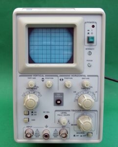
While the typical multimeter only measures voltage, current, and resistance value, an oscilloscope can give you more information regarding the voltage and current, including its waveforms graphically. From those displays, the data about amplitude, frequency, rise time, time interval, and distortion can then be acquired.
To operate it, the user must connect a probe to one point of a circuit or component and another probe to the ground.
Up till now, there are two types of oscilloscopes, which are Cathode Ray (CRO) and Digital Storage (DSO). The cathode ray is the older type, which has fewer features than the digital storage type. The digital type, as known as the modern type, has richer features that make the users more comfortable while using it. As an example, the modern model makes it possible to save the waveforms captured to the flash disk via USB connectivity.
Nowadays, an oscilloscope is more portable as the handheld model allows you to carry it around on the worksite.
Further reading: Top 10 Best Best Oscilloscopes Reviews
11. Frequency Counter
A frequency counter is used for measuring the number of oscillation cycles of a complete electronic waveform. The use of frequency counter is vastly needed in various fields to measure the repetitive signal frequency and the time between edges of digital signals.
There are several kinds of frequency counter available in the market. The bench frequency counter is the most used by the community for electronic test equipment. There is a time when the frequency counter is needed in a PXI format. The PXI type has the best compatibility for measurement and automation because of its high-performance and rack system. The users of the frequency counter are not always working inside of a laboratory. Some work outside or in the field. The field engineers find it best to use the handheld type of frequency counter for fieldwork. Some digital multimeters also include the feature of a frequency counter. However, most of them are relatively basic and far from the typical frequency counter. A panel meter is the type of frequency meter provided in panel mount modules. With this kind of mounting, it makes them possible to integrate with a larger set of equipment.
12. EMF Meter
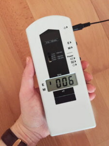
To measure the ambient electromagnetic fields, the meter we need is called an EMF meter. In practice, the EMF meter is basically sensors or probes. The electromagnetic field measured by the EMF meter is produced by alternating current (AC). The main purpose of using an EMF meter is to detect problems in power lines and electrical wiring.
The basic working principle behind it is by measuring the changes in electromagnetic flows in the field. By doing so, the troubleshoot for electrical wiring, and power lines can be conducted. There are two different kinds of EMF meters. The single-axis meter is used to measure the electromagnetic field strength in one direction only at a time. To get the best measurement, the user must measure in various orientations to get the most reading. The tri-axis meter measures the electromagnetic field in three single-axis (x,y, and z) and calculate them to produce the resultant reading.
Looking for an EMF meter or detector to measure the radiation? Get the list of these Top 10 Best EMF Meter Reviews.
13. Gaussmeter
There are two ways in which the electromagnetic fields are generated. It can be through the direct current and alternating current. While the EMF meter measures AC electromagnetic fields, the gaussmeter is the one to measure DC electromagnetic fields. The units used by a gauss meter to measure the electromagnetic field are Gauss (G), miligauss (mG), miliTesla (mT), or microTesla (uT). Most of the available products are designed simple so that it eases the users in doing the measurements.
There are two types of gauss meters. The vector type is useful to measure the magnetic field direction around the equipment. On the other hand, the scalar meter is used in measuring the magnitude of the magnetic field around the test tool.
Further search: Top 10 Best Gaussmeter Reviews
14. Spectrum Analyzer
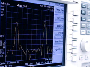
The core function of this instrument is to measure and capture the input signal in the frequency domain in the full instrument frequency range. From that point, the power of both known and unknown spectrum can be measured. The real-life application of spectrum analyzer varies from basic pre-compliance test for EMC, occupied bandwidth and sources of interference, frequency response, noise, and distortion characteristics in radio-frequency circuitry.
Based on the architecture, spectrum analyzers are categorized into three types.
- Swept spectrum analyzer. It is the older architecture and great at observing static signals. It provides a high dynamic range for amplitude calculation. While the downside is it is only able to calculate the amplitude in one frequency at one time.
- Vector signal analyzer. It is primarily used to analyze signals which carry digital modulation. The reason is it provides both magnitude and phase information. The downsides it has are its limitation to analyze transient events, isolation of weak signals caused by the existence of the stronger signals, and signals whose frequency changes but not its amplitude.
- Real-time spectrum analyzer. It is a high-speed diagnostic tool that uses a Fast Fourier Transform (FFT) technology to analyze signals, making it more powerful and able to cover the incapability of the older model of the spectrum analyzer. By using RTSA (Real-Time Spectrum Analyzer), a small narrowed signal can be detected and no gaps are missing to scan through due to its high-speed measurement.
15. Logic Analyzer
A logic analyzer is a test instrument to monitor and investigate multiple signals from the digital or logic circuit under test. The development of the first logic analyzer was mainly needed to debug and find faults in microprocessor-based systems. Meanwhile, in the 1980s, the current oscilloscope didn’t have such that ability to provide suitable functionality levels. The typical logic analyzer has some characteristics such as multiple channels, providing a time display of logic states, and providing no display of analog information.
While its development is still going on, there are three primary types of logic analyzers as of now. The modular type is the one called the typical logic analyzer, which provides the highest functionality level. Meanwhile, the portable type is the right model for those who are restricted in budgets and in dire need of field service. The last type would PC based model that connects through USB and Ethernet. This model can reduce the overall system cost and offer high-performance levels.
Read further: Oscilloscope Vs. Logic Analyzer
16. Transistor Tester
A transistor tester is a test instrument to know the electrical behavior of solid-state diodes and transistors. There are three main types of transistor tester in practice.
The first is a circuit tester. This type is used to check the transistor inside a circuit to determine whether it is already dead or operational. Using this type requires the user not to remove the transistor from the circuit.
The second type of tester performs three kinds of checks: transistor gain, leakage current, and short circuit test.
The last type is the laboratory standard tester. It is primarily used to measure transistor parameters under different operating conditions. The characteristics measured are collector current with an open emitter, common emitter, and input resistance.
17. USB Tester
People mainly use this instrument to test the USB connections to find problems with ports, phones, cables, or chargers. It is designed for home, auto, and office. The size of the USB tester is a compact model, which can fit in a pocket. Thus, that is going to make it convenient and easy to use.
A typical USB tester uses an LED color as an indicator or status. Those are amber for AC voltage present, red for reversed polarity, green for port OK, and not lit for a dead port.
18. USB Multimeter
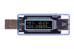
The USB multimeter has a size almost as small as a USB tester. The similarity between the two is both can test and confirm USB port function. However, the USB tester uses the LED as an indicator. Meanwhile, the USB multimeter has a small display screen to show the voltage, current, and other measurements such as speed charging, charging time left, energy use, etc.
As a matter of fact, you can say them as USB meter. Moreover, when you search on the web trying to purchase a new USB tester, you are served with USB multimeters on the search result. People may end up buying the USB multimeter even though they are actually looking for a USB tester. This is not a problem because the USB multimeter has the basic function of the USB tester has and it provides more while the price doesn’t rob the buyers.
19. Wire Tracer
Wire tracer is used and designed to locate wires in areas where it is hard to reach or invisible by eyes. It helps you to save a lot of time finding the troubled wire. As a result, a trouble wire buried in the wall, earth, etc., can be repaired quickly.
There are two types of wire tracers. Active tracing is great for users who need to pinpoint specific pipes, lines, and cables. Its working principle is the device is going to emit a signal through direct attachment with the test subject or to be well-positioned on the ground. On the other hand, passive tracing is done when the targeted line is already supplied with electricity. Then, it detects the signal power in a specific area.
Typical wire tracer lasts for a long time mostly. Thus, it is such a good investment for you. Moreover, the price is not high. However, if you purchase the model designed for underground wire or cable, the price can skyrocket according to the features it provides.
20. Continuity Tester
The main function of this test instrument has is to check the connectivity of a circuit. It is a device powered by batteries. It is equipped with a probe at one end and a cord (either an alligator type or another probe). The light on its body will be switched on when you connect the two together.
To operate it, the device or circuit under test must be switched off or disconnected from the power supply. In a real-life application, a continuity tester is great to check if the lamp wiring or circuitry is working properly. Aside from that, people can also use it to detect the short circuits. It is not expensive and surely useful for those who want to do some houses’ electrical work from the price aspects.
21. Test Light
A test light is the electronic test equipment mainly used to identify the electricity presence of a device under test. It needs less cost and is more simple than a typical multimeter. The test light with good design must protect the user from possible electric shock.
The test light can be connected with one or two wire leads. The working principle is really simple. The test light will turn the lamp (bulb) on when the electricity is present. The technicians most use it as part of the safety procedures in doing electrical maintenance.
Today’s test lights come with voltage reading, which is a great extra advantage.
22. Network Analyzer
This measurement tool makes it possible for the users to observe the network parameters in the electrical network. S-parameters are the most measured by this instrument as they are easier to measure at high frequency.
The reason why we need to analyze the network is to permit us to make the characterization by knowing the network response through an RF network analyzer.
There are three types of network analyzers. Scalar type just measures the amplitude of the RF device. Vector type measures both amplitude and phase. The last one, the large signal type, is the exclusive type that examines the device parameters under large-signal climates.
There are some differences between network analyzers and spectrum analyzers. The first difference is network analyzers send the signal and analyze the device that receives it. On the other hand, spectrum analyzers only analyze an applied signal.
Moreover, the network analyzer consists of many receivers and source-receiver to measure the broadband frequency with the method of sweeping power and frequency. Thus, its measurement is more precise than the spectrum analyzer. On the other side, a spectrum analyzer only measures the parameter of a signal, not a device. The spectrum analyzer has more flexibility for allowing a complete range of signal analysis. The network analyzer measures the reflection, insertion loss, S parameters, return loss, and transmission, which deals with the device components measurement. The spectrum analyzer measures noise harmonics and power level.
There is also a difference in utility. A network analyzer is used in RF design laboratories. It lets designers understand many features and performances. Because of its high price, it is not used in production. Spectrum analyzer is mostly used to test the electronic filter circuit. It is already equipped with a tracking generator for scalar component testing usage without phase measurements.
Conclusion
Describing every electronic measurement instrument indeed takes a lot of time. However, we shift our focus to summarize every bit of information about them. Therefore, the summary sections exist inside this article. Every single thing described above is the common thing to know in electronic measurement.
We gather the information through our real-life experience, knowledge, and some reliable sites from the internet. We have high expectations that this article will help the readers improve their knowledge and skill in electronic measurement.
