
Cosine error occurs in the dial indicator when the direction of measurement of an object is at a certain angle (not as it should be) against the tip of the dial indicator. As the angle increases, the value of cosine error also increases.
This error is small in value but it’s considerable when we want to measure the accurate values of precision objects like the thickness of the surgical knife blade, size of the piston of the automobile, and the mating shafts of the watch. All these parts and many more items require high precision to operate them as per the designed function. If we deviate one-fourth of millimeters of the designed size, we may not achieve desired results.
Therefore, knowledge of cosine error is essential to measure the accurate dimensions of the objects. As this error can present in all the measurements of dial indicators, however, you can reduce even eliminate it by applying proper procedure.
To explore the causes of cosine error in the dial indicator, first, we need to get an overview of the dial indicator itself.
Basic Things You Have to Know
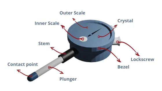
Before going further, there are some basic things that you have to know: the dial indicator types and their body parts.
Why is it important?
As we know that there are two types of dial indicators based on how their contact tips move: dial indicator (DI) and dial test indicator (DTI). Since dial indicator and dial test indicator are different, the way of cosine error happens to these two indicators is also different.
The dial indicator’s plunger (and the screwed contact point as well) goes in and out from the stem. This mechanism asks you to position the plunger perpendicularly towards the surface being measured. If the plunger has a tilt toward the surface, the cosine error will be present.
On the other hand, the dial test indicator’s stylus (where the contact point takes place) swivels. This mechanism asks you to position the stylus parallel to the object’s surface. If you put them not parallel, the cosine error will be present as well.
In essence, the cosine error happens in the dial indicator (DI) when it’s not perpendicular. Meanwhile, the cosine error happens in the dial test indicator (DTI) when it’s not parallel.
Why Does Cosine Error Occur?
As said before, the reason behind the cosine error in the dial indicator is the misalignment of the axis of the contact point and the stylus/plunger to the object surface being measured.
Suppose if we measure the object who has an original thickness of 0.5 mm being measured with a dial indicator. The contact point is making 0 degrees of angle with respect to the measuring surface. In this case, we get an accurate value and the cosine error is zero.
If we slightly increase the angle to 1 degree of the contact point with the object we get 0.500076 mm (≈0.50008 mm). This is an increase of just 8 nanometers. Furthermore, if we measure at an angle of 2 degrees, we get 0.5003 mm and the error is 30 nanometers. Likewise, 3 degrees of angle shows a reading of 0.500686 mm (≈0.5007 mm). Lastly, if we measure the same object at an angle of 4 degrees, we get 0.5012 mm. It’s an error of 0.12 micrometer.
From these examples, we can understand that the cosine error occurs due to the angle of the contact point to the measuring surface.
Another way to understand why cosine error happens is because it’s lifted less but the plunger moves more.
For example, if you measure a .25″ feeler gauge using a 60° tilted dial indicator, you can see that it displays a reading of .5″. That is because it’s lifted for .25″ (the thickness of feeler gauge) but the plunger has moved for .5″. As Cosine 60° is 1/2, it’s easy to understand that the lifting is half of the plunger movement.
How to Measure the Cosine Error
Don’t panic! It’s easy.
Formula
The initial formula to gain the cosine error is:
Cosine Error = Displayed Reading − Actual Reading
Remember that:
Actual Reading = Cosine θ × Displayed Reading
Because the only known is the angle tilting while the actual reading is unknown, then:
Cosine Error = Displayed Reading − ( Cos θ × Displayed Reading )
Let’s calculate!
Cosine Error of 1°
Suppose that the dial displays a reading of .5″ but your plunger tilts for 1°. Calculate the error?
Cosine Error = Displayed Reading − ( Cos θ × Displayed Reading )
Cosine Error = .5″ − ( Cos (1°) × .5″ )
Cosine Error = .5″ − .499924″
Cosine Error = .000076″
In this case, this error doesn’t have an impact on the dial indicator, even for those that come with a resolution of .0001″.
Cosine Error of 2°
Suppose that the dial displays a reading of .5″ but your plunger tilts for 2°. Calculate the error?
Cosine Error = Displayed Reading − ( Cos θ × Displayed Reading )
Cosine Error = .5″ − ( Cos (2°) × .5″ )
Cosine Error = .5″ − .499695″
Cosine Error = .000305″
In this case, this error can easily mislead the dial indicator reading, especially the indicators that come with a resolution of .0001″.
Cosine Error of 3°
Suppose that the dial displays a reading of .5″ but your plunger tilts for 3°. Calculate the error?
Cosine Error = Displayed Reading − ( Cos θ × Displayed Reading )
Cosine Error = .5″ − ( Cos (3°) × .5″ )
Cosine Error = .5″ − .499314″
Cosine Error = .000686″
Surely, your .0005″ resolution dial indicator can give a false reading in this angle error.
Cosine Error of 4°
Suppose that the dial displays a reading of .5″ but your plunger tilts for 4°. Calculate the error?
Cosine Error = Displayed Reading − ( Cos θ × Displayed Reading )
Cosine Error = .5″ − ( Cos (4°) × .5″ )
Cosine Error = .5″ − .498782″
Cosine Error = .001218″
It’s no doubt that even your low-resolution dial indicator (.001″ resolution) can display misleading reading if the plunger tilts for 4°.
Cosine Error of 5°
Suppose that the dial displays a reading of .5″ but your plunger tilts for 5°. Calculate the error?
Cosine Error = Displayed Reading − ( Cos θ × Displayed Reading )
Cosine Error = .5″ − ( Cos (5°) × .5″ )
Cosine Error = .5″ − .498097″
Cosine Error = .001903″
If this angle error happens and your reading shows .007″, the accurate reading is actually .005″. The error is highly considerable even for low-resolution dial gauges.
Conclusion
From the above discussion, we can conclude that cosine error can mislead the reading. If you have a high-resolution dial indicator (.0001″) and your cosine error is 2°, your reading has a chance of error up to .0003″. For this high-resolution dial indicator (Mitutoyo 2358S-10), this error highly impacts the measurement accuracy. However, we can ignore it if our dial indicator has a low resolution (.001″). In case of a cosine error of 4°, it can mislead about .001″ to indicators, even the lower resolution ones (.001″).
If you want to calibrate a dial indicator, this error has to be your concern as well.
Other posts under the category “Dial Indicator”:
- What is Dial Indicator? – These are the Measurements that Dial Indicator Handles
- Dial Indicator Body Parts: Internal and External Parts
- Types of Dial Indicator: According to These 3 Factors
- Dial Indicator Vs. Test Indicator: the Plunger and the Lever Models
- How to Use Dial Indicator
- What is Cosine Error? – How Far Its Impact on the Measurement Accuracy of A Dial Indicator
- How to Read Dial Indicator: Reading the .001″ and .0005″ Resolution
- Dial Indicator Calibration: How to Calibrate the Dial Indicator
- Best Dial Indicator Reviews: Top 10 Products
- Best Test Indicator Reviews: Top 10 Products
- Best Dial Bore Gauge Reviews
- Best Digital Indicator Reviews
