
Dial indicators, or dial gauges, are mechanical display instruments used to provide a reading of some tiny distance that are not visible to the naked eye.
As the name suggests, a dial indicator is a measuring tool that possesses a dial scale reading. There are a rotating pointer and a circle scale of equally-distanced numerical markings (positioned at the edge). That is similar to a clock face.
It’s easy to notice that there are 2 pointers (long and short) and 2 scales (outer and inner) on the dial. Aside from that, there are some other parts such as crystal, plunger, contact tip, bezel, screw, etc. These parts make the dial indicators look more distinguishable.
Inside of the dial indicators, a rack and pinion gear is included to read its probe position and display over the graduation scale.
External Components of A Dial Indicator
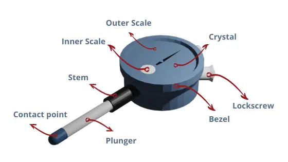
1. Case & Crystal
It is the outermost part of the dial indicator, typically made of a clear plastic lens. It is right above the pointers and scales and protects them from external materials such as your hand. Bezel and outer frame hold it. Crystals are very comfortable with both excessive sunlight vision and dim light vision. It is replaceable and you should replace them easily.
2. Bezel
It is the outer circular part of the dial indicator. It can be both plastic or metallic. Few of the dial indicator has rubber bezel. It normally used to set the zero-reference on the inner dial face. Its surface is rough and movable. After you set the zero-reference, you use the top screw to tighten the bezel.
3. Outer Scale
There are two scales inside: the outer scale and the inner scale. The larger one (the outer scale) is the most contrast scale compared to the inner scale. It’s the scale where the longer pointer points to. Its position spreads over at the edge of the scale circle.
Commonly, it consists of 100 divisions. Each division represents the smallest graduation (resolution) the dial indicator has. If you are going to take the reading of a dial indicator, the reading of the outer scale must be counted.
Most dial indicators come with 0.001″ resolution and 100 division scale, which means a full rotation of the long pointer (passing through the 100 divisions) counts 0.1″. Further, the long pointer must rotate 10 times to get a reading of 1″ (the total measurement range).
If it comes with a 0.001″ resolution and 50 division scale, then one complete spinning counts 0.05″ and the pointer must rotate twice to get a reading of 0.1″. Further, the long pointer must rotate 20 times to get a reading of 1″ (the total measurement range).
4. Inner Scale
The second scale is the inner scale. This scale has a smaller size and commonly positioned somewhere between the center and edge. At the center of the inner scale rotates the short pointer.
This scale gives you a reading of how many revolutions the long pointer has taken. Therefore, when making a TIDY calculation, you have to count the reading of the inner scale first.
As our observation on the currently several dial indicators on the market, most of them come with a different amount of scale divisions. Some of them come with 10 divisions, while some with 5 divisions.
For the 5-division scale, the short pointer has to rotate 2 twice to get a full 1-inch reading. While the 10-division model, a single rotation is a 1-inch reading. However, things may become different if the dial indicators provide more than a 1-inch range measurement.
5. Long Pointer
There are two pointers (needles) inside: the longer pointer and the shorter pointer. The longer pointer functions to point out a numerical marking on the outer scale. In terms of the material, long pointers can be made of metallic or plastic. This needle (long pointer) is highly sensitive. A very tiny movement of the plunger will move this pointer.
6. Short Pointer
As mentioned before, the short pointer belongs to the inner scale. It rotates at the center of the inner scale. Its function is to point the numerical markings on the inner scale and gives a reading of how many rotations the long pointer has passed through.
7. Lug Back
Lug means ear. That said, lug back means the back which looks like an ear. Lug back helps to hold the dial indicator with the magnetic base stand. Without this part, it’s very hard to take accurate readings. If you want to slide the bezel, it will be stable in all directions. Lug back helps to hold still at any position.
8. Top Locking Screw
When you have to change the zero reference, it means that you have to slide the bezel. To be able to slide the bezel, you have to unscrew this lock to perform that. Afterward, you have to screw the lock again. The position of this lock is at the top of the dial indicator.
9. Contact Point
The contact point is located at the lower part of the dial indicator. This is the dial indicator part where the surface of the object being measured and the dial indicator meets. A contact point should be made of durable material to get an accurate reading. Today’s dial indicators take advantage of carbide. This is the same as what happens to micrometers’ anvil.
10. Plunger & Stem
Together with the contact point, the plunger moves in and out. When no pressure is gained by the contact point, the plunger will move out completely from the stem. Vice versa, when pressure is applied (measuring mode), the plunger will move in.
The plunger also behaves to hold the contact point. Imagine that plunger must be made of carbide, this is not an effective way in terms of cost production, in our perspective.
The movement of the plunger makes the rack to transfer the movement to the pinion, pinion transfers to the gear. Finally, with the help of the pointer attached with the gear, the operators are able to enjoy the measurement reading.
11. Frame
The frame is also one of the most important parts of the dial indicator. It is the main structure of the dial indicator. It is normally metallic and protects all the equipment inside.
12. Base Metal
The base metal is a very important part of a dial indicator. The basement holds all the gears and pinions. This part is normally made of metals. It needs to be very hard and stable.
Internal Parts and Mechanism
Internal parts of the dial indicator consist of several gears, rack, pinions, plunger, and springs. You could see the following picture. Keep in mind that each dial indicator brand may have its own construction. Here we give an example. There are 3 gears and pinions mentioned in the diagram.
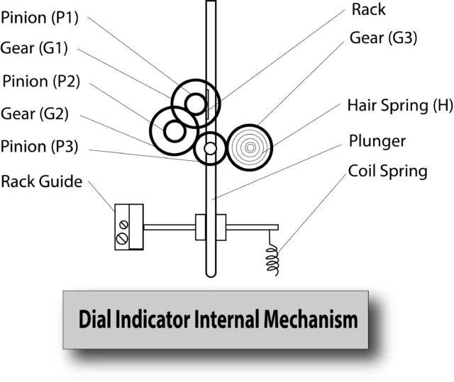
First of all, they have a plunger rod attached to the gears and the pinions. The lowermost point is known as the contact point. Here is where the object surface and indicator meet. Then, with the movement of the rod, the rack also drives the pinion 1 (P1), P1 then drives the first gear G1. Following this, G1 drives pinion 2 (P2). Afterward, P2 drives G2. And then G2 drives P3. Further, P3 drives the longer pointer.
P1 -> G1 -> P2 -> G2 -> P3 -> longer pointer
Later on, the P3 has the pointer on the outer scale. While P2 got the hand (shorter pointer) on the inner dial display. The hairspring let the pointer comes to its original position after the measurement. Coil spring lets the plunger go to its original position after it is detached from the object surface.
You could learn from the following video about the real appearance of the internal part of a dial indicator. In this case, it is Starret 25-341.
Summary
Among the indicator models that exist, we are sure that the dial indicator is the most used. There is another model called the digital indicator.
Those are the parts of the dial indicator in general. There are internal and external parts. The internal parts are hopefully easy to understand if you are learning the working mechanism of a dial indicator. At that point, you could understand how both the short and long pointer work together to show us the reading.
There are some important parts of the dial indicator which are:
- Case: It is a metallic casing that is the skin of the dial indicator.
- Graduated Scale: Inside the casing, a graduated scale is present in which different readings are marked.
- Pointer: A pointer is present inside of the dial indicator which points at the measured value on the graduated scale and provides reading.
- Stem: The plunger or spindle moves up and down inside this stem according to the size of the object to be measured.
- Contact Point/Tip: This contact point or tip of the indicator will have contact with the surface and will help in the movement of the plunger.
Other posts under the category “Dial Indicator”:
- What is Dial Indicator? – These are the Measurements that Dial Indicator Handles
- Dial Indicator Body Parts: Internal and External Parts
- Types of Dial Indicator: According to These 3 Factors
- Dial Indicator Vs. Test Indicator: the Plunger and the Lever Models
- How to Use Dial Indicator
- What is Cosine Error? – How Far Its Impact on the Measurement Accuracy of A Dial Indicator
- How to Read Dial Indicator: Reading the .001″ and .0005″ Resolution
- Dial Indicator Calibration: How to Calibrate the Dial Indicator
- Best Dial Indicator Reviews: Top 10 Products
- Best Test Indicator Reviews: Top 10 Products
- Best Dial Bore Gauge Reviews
- Best Digital Indicator Reviews

This is a great post for anyone who is looking to learn more about dial indicators. The author does a great job of explaining the different parts of a dial indicator and how they work together. This is definitely a post that I will be referring