
Accuracy and simplicity are two priority things in metalworking. And that’s why designers and engineers use varieties of measuring tools in workshops.
There are a lot of tools we might need to design our complete model. And thus, we are here to summarize each of the tools we might need in metalworking workshops.
In each measurement tool summary, you will get a general idea of the specific instrument and its uses. Moreover, we will describe the functional characteristics of each of the tools. Please continue reading, and we hope you will get everything that you need to find.
26 Workshops Measuring Tools
Before we jump into details, we suggest you have a look at the following table. This table contains each of the functional characteristics of the measuring tools.
| Name | Function |
| 1. Angle plate | Marking, Adjustment |
| 2. Bore gauge | Hole/Bore Measurement |
| 3. Calipers | Breadth, thickness, and depth measurement |
| 4. Center gauge | Used in lathe machine, angle reformation |
| 5. Combination square | Marking 90° and 45° adjustment |
| 6. Coordinate-measuring machine | Specifies position on a linear surface |
| 7. Cylindrical-coordinate measuring machine | Specifies the position in a cylindrical object |
| 8. Drawbar force gauge | Force analysis |
| 9. Feeler gauge | Gap widths |
| 10. Gauge block | Measuring standard |
| 11. Height gauge | Determining the height of an object |
| 12. Dial Indicator | Run-out, deck clearances, thrust, surface linearity |
| 13. Machinist square | Squareness checking, adjustment of the proper alignment |
| 14. Marking gauge | marking to cut out, woodworking, and metalworking |
| 15. Optical comparator | inspect and measure the dimensions of small manufactured parts |
| 16. Profilometer | surface roughness measurement |
| 17. Radius gauge | measure the radius |
| 18. Sine bar | an angle very accurately or face locate any work to a given angle |
| 19. Snap gauge | justifies the dimension of separate parts |
| 20. Square (tool) | the correctness of the 90 degree angles |
| 21. Straightedge | for drawing straight line, checking straightness |
| 22. Surface plate | precision inspection, marking out (layout), and tooling setup |
| 23. Tape measure | to measure distance and displacement. |
| 24. Thread pitch gauge | reference tool in determining the pitch |
| 25. Wiggler (tool) | edge-finder, center-finder or laser-centering-device |
| 26. Tachometer | Inspect the RPM speed of your machine |
| 27. Protractor | Measure the angle of object’s edge |
1. Angle Plate
An angle plate is generally a holding device used to fit different parts in metalworking. The materials used for this instrument are high-quality spheroidal cast iron. For this reason, the rigidity of the component stabilizes the prevention of further movement or distortion between the separate parts and mechanism.
There are two kinds of angle plates you may find in today’s engineering world. They are adjustable angle plates and fixed-angle plates. The main difference between these two angle plates is the adjusting method. An adjustable angle plate can fit any sizes near its range. On the other hand, the adjusting knob of the fixed angle plate is rigid and unchangeable.
Angles are generally beneficial for secure attachment while marking out the different points and shapes for different designs and cutting. Angle plates are available on many of the super online markets.
2. Bore Gauge
The bore gauges are usually the measuring tools used to measure the different dimensions or bore. Once we insert this measuring tool inside the bore, the instrument’s anvil expands; and we can determine the radius of the hole. We can perform a few tests using bore gauge, such as hole tests, bore mics, cylinder test, hold bore gauges, internal micrometer, etc.
You may find different kinds of bore gauges depending on the accessibility and digitalization, such as telescopic gauges, small-hole gauges, Beam gauges, inside micrometers, and dial bore gauges.
3. Calipers
Calipers are very popular among students and engineers. You can use calipers in different linear measurements such as measuring length, width, the diameter of holes, and depth of holes. Calipers can have a resolution down to 0.01 mm (0.0005″), pretty accurate and straightforward.
In addition, calipers also have different types such as inside calipers, outside calipers, divider calipers, oddleg calipers, vernier calipers, dial calipers, digital calipers, and micrometer calipers. However, the most used ones that we know are the vernier caliper, dial caliper, and digital caliper.
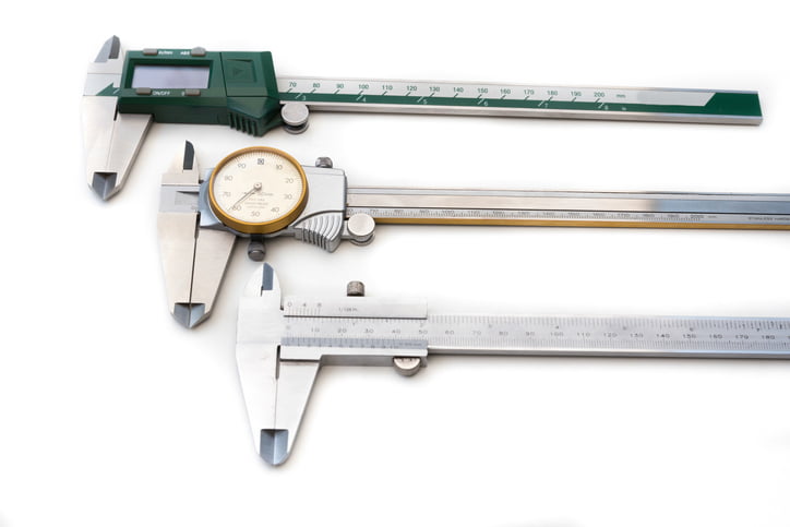
When it comes to vernier caliper, there is a moving scale called the vernier scale that determines the decimal values after the real deals. Due to some physical properties, the vernier scale may have zero error. Physical properties like rusting, compression and expansion, external damage, etc. If there have any external damage, we should follow “actual reading = main scale reading + vernier scale reading ± zero error.”
Dial caliper and digital caliper, on the other hand, give you faster reading rather than the vernier but generally charges you more. In terms of displaying the reading, the dial caliper uses a dial scale, while the digital caliper uses an LCD screen.
4. Center Gauge
These types of measuring tools are usually for lathe work operations. Center gauges and fishtail gauges check the angle while grinding the object’s profile. These two gauges are outstanding for hand grinding threading operations. Center gauges are convenient for grinding and setting thread cutting tools.
On the other hand, these instruments are made of stainless steel with satin chrome finished. Besides, they have two different item codes, such as ABM-EPT-9305 is for 55° whit worth measuring standard, and ABM-EPT=9306 is for a 60° US standard measuring system.
5. Combination Square
A combination square has two different main parts: ruler and head. The ruler has a moving rail on which the heads can move in forward and reverse direction. Usually, the ruler has the metric, imperial, or both metric and imperial measurement system. There are two types smaller one can measure up to 150mm or 4 inches, and the larger one can measure up to 24 inches.
The heads can have multiple structures depending on the use of the designers. You can use the standard head as a square for 90° and 45° angles and check the surface straightness and flatness.
6. Coordinate-measuring Machine
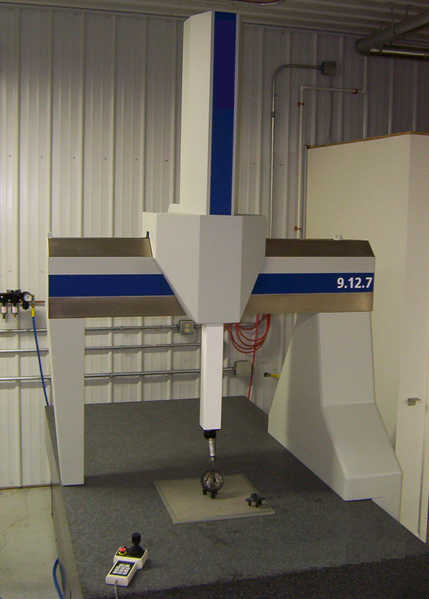
A CMM (Coordinate Measuring Machine) is a measuring device that locates physical objects’ geometry with a probe. The CMM uses various sensing types such as optical, laser, and white light. Using these sensing type CMM, an object’s position on a three-dimensional Cartesian coordinate system (XYZ axes).
The CMM has three main components: the main structure, the mechanical probe (the probing system), and the data collection and reduction system. The CMM follows the ISO 10360 series of measurement systems.
7. Cylindrical-coordinate Measuring Machine
The CCMM has a similar task as the CMM does. But the only difference is the CMM can not specify the position in cylindrical objects. It incorporates a moving table relative to the probe to rotate the part. The probe tool can only move in the Z direction in the probe mechanism when it omits the X and Y axes. On the other hand, when the probe tool moves in X, Y axes, it misses the Z axes.
The CCMM is standard for cylindrical parts such as camshaft, crankshaft, transmission shafts, and some other rotating parts. Cylindrical CMM follows ISO 10360 legal measurement system.
8. Drawbar Force Gauge
Force is an essential physical quantity we need every day. Therefore, maintain this force is also a vital and necessary part of the machine.
A drawbar force gauge helps us determine the pressure on a machine tool’s drawbar. We know many modern devices provide more than 50000 Newton of forces. If something went wrong, there some accidents might happen. So, In this case, the drawbar force gauge helps us determine the exact force and figure out how to maintain those forces.
Drawbar force gauge generally has a dial indicator to represent the amount of force determined from the drawbar. This indicator can be dial or digital depending on modern digitalization. This product is available in most of the famous online market.
9. Feeler Gauge
Engineers and designers usually use a feeler gauge to measure the gap between the shafts or sides. A feeler gauge is used in metalworking to measure the clearance between two parts or components in an easy way.
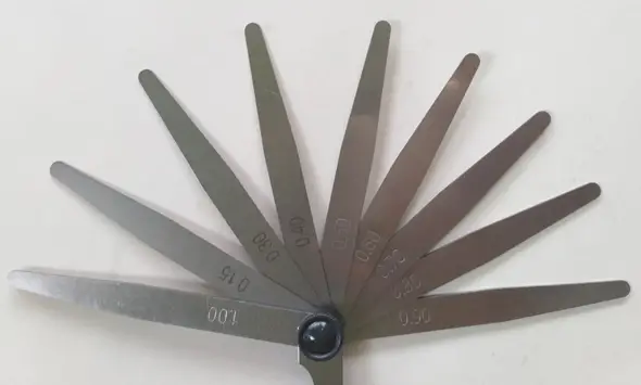
There is a set of different thickness sizes of feeler gauge available in a group. The materials used for this measuring tool is stainless steel with satin chrome finished. But, you may probably find it made from another material as well.
Feeler gauge can be two different types based on their shapes: the tapered and parallel one. Each of the feeler gauges has commonly both metric and imperial measurement systems on the surface to indicate its thickness.
10. Gauge Block
Gauge block is the practical standard for a length that we can use in the workshop (be it machining or woodworking workshop). Micrometer, caliper, dial indicator, and depth gauge take advantage of gauge block for inspection and calibration. So, before operating those precision measuring instruments, inspecting them with calibrated gauge blocks is a must to ensure accuracy.
The gauge block can be a single block or a set. A set of gauge blocks consists of several different dimensions. The more variety of dimensions, the better it is. If you only have several blocks, you may need to wring some blocks to get the length that is unavailable in your set.
Besides, they come in a certain grade. The grade lets you know its accuracy. So, you know what grade to buy and what projects the gauge blocks are ideal for.
The materials used for each of the gauge blocks are tungsten carbide, chromium carbide, or ceramic.
When we need a gauge block, we gently put them out and clean them with petroleum jelly or oil. The manufacturer assured that the gauge block calibrates accurately at 20°C. In this case, the effects of thermal expansion may provide tolerances. Thus, the machinist suggests calibrating at this temperature. The gauge blocks from various manufacturers worldwide are available on the online market.
11. Height Gauge
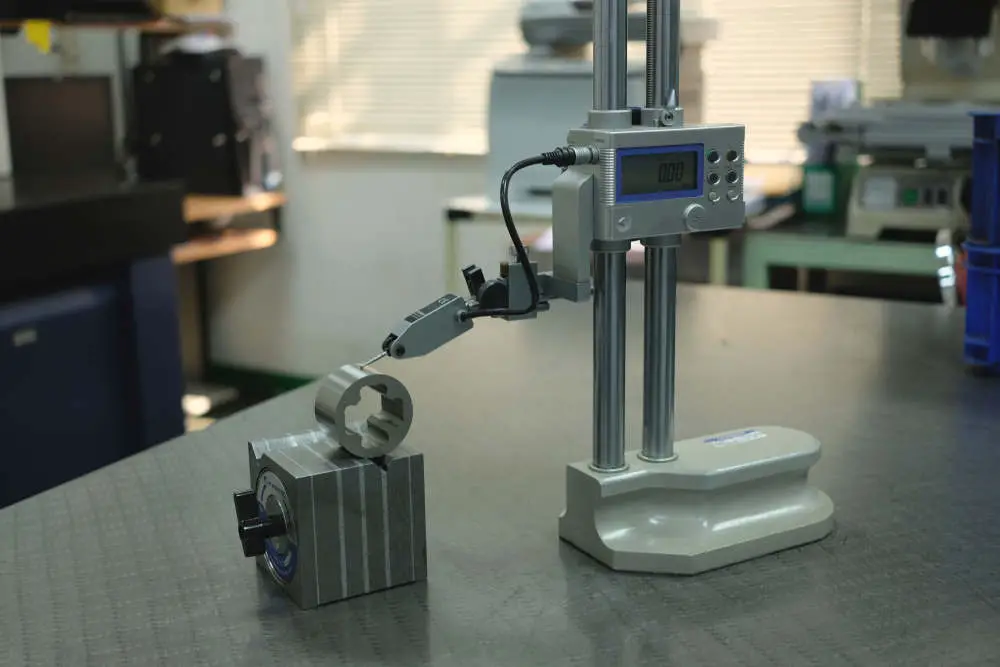
We know that gauge blocks are for measuring the lengths to produce metal objects. But do you know how to determine the height standards? In this case, we use a height gauge. It is usually beneficial for determining the height of objects. Have you seen a measuring instrument to find the height of a patient in a clinic or hospital? That’s one type of height gauge.
Consequently, height gauge has a sharp pointer to define the accurate position of the pointer. Height gauges measure the height of an object by the scriber underside as a datum. You may get confused between a height gauge and a surface gauge. Well, a height gauge has a measurement head. On the other hand, the surface gauge has a scriber point only.
12. Dial Indicator
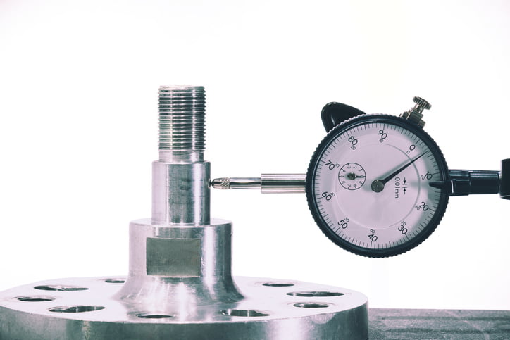
A dial indicator is one of the most popular measurement tools both in metal and woodworking places. It usually measures the surface’s flatness, roundness, and run-out tolerances. The pointer moves up and down depending on the exact position on the object’s surface. Due to this movement, the gears transfer the linear movement into the indicators’ circular movement.
Based on the indicator and measurement mechanism, dial indicators have several types. They are balanced reading dial indicators, continuous dial indicators, revered balanced dial indicators, reverse continuous dial indicators, dial test indicators, plunger dial indicators, lever dial indicators, etc. Dial indicators are highly demandable nowadays. Make sure you have learned more about how to read a dial indicator.
A dial indicator can also be installed at the top of a bore gauge as the readout. The movement of the needle gives you a visual reading which is one of the major advantages of using a dial indicator.
13. Machinist Square
If you visit any metal or wood workshops, you will see that engineers and machinists use this precision tool to check for squareness and perpendicularity. A machinist square or engineer’s square consists of a solid blade and stock forming an L-shape at an angle of 90°.
Unlike other square tools, machinist square has tight accuracy and less error. Its perpendicularity is only off a little. If you require a high degree of squareness and perpendicularity, use this tool.
14. Marking Gauge
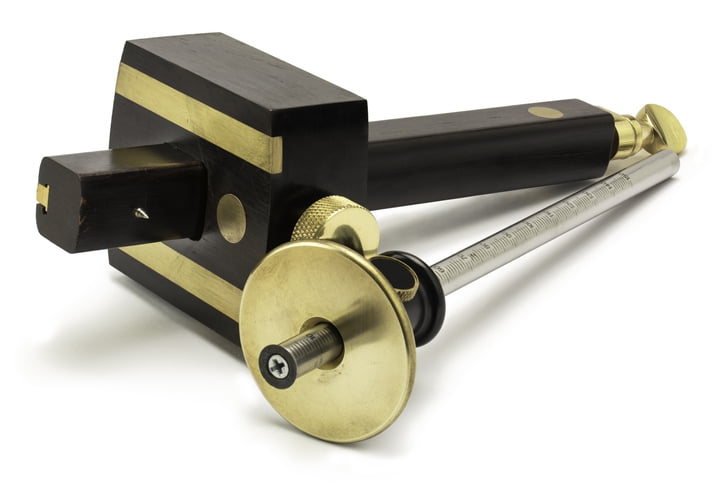
A marking gauge is also popular in woodworking and metalworking places. It usually makes an alignment parallel to the reference edge or surface. There’s a pointer at the headstock that helps to mark the required aligned places. In general, a marking gauge helps mark the outline for cutting purposes.
The marking gauge structure consists of three different regions: headstock, beam, and a lever or a wedge. There is a variation of marking gauge, the marking gauge with a knife instead of a marking pen is the cutting gauge. Other variations are panel gauge, mortise gauge, etc.
15. Optical Comparator
If you are familiar with engineering drawing, you will easily catch the working principle of this machine. We know we need different views to understand the dimension of an object completely. And thus, an optical comparator helps us determine the dimension of an object. This machine follows the principle of optics to inspect the dimension of the projected object.
There are magnifying glasses that reflect the projected beam to create a two-dimensional sketch. Optical comparators’ features include projection methods, positive or inverted images, screen sizes, magnification, worktable, and accessories. This machine is expensive than any of the measurement tools for metalworking. But yet it is advantageous.
16. Profilometer
If you graduated as an engineering student, you would know this machine and its mechanism. In a bachelor’s degree, every engineering student learns how to operate this machine to determine an object’s surface roughness.
Anyway, a profilometer is a computerized machine that determines the surface roughness. To solve various tolerances such as step, curvature, and flatness, we use a profilometer by finding its roughness.
Profilometers can have different types; they are: digital holographic microscopy, phase-shifting interferometry, vertical scanning interferometry, and differential interference contrast microscopy are the most common.
On the other hand, based on other factors, we can classify the profilometer into a few more types. They are contact profilometer, Non-contact profilometers, Time-resolved profilometers, Fiber-based profilometers.
17. Radius Gauge
The radius gauge has another name as a fillet gauge. This is a metalworking measuring tool we use to determine the radius of an object. It requires bright light to measure behind the object. Remember to place the radius gauge against the edge so that you can easily determine the value of any light leakage between the blade.
Generally, the materials used for this instrument are stainless steel. One set of radius gauge consists of both concave and convex sections of the blade. The radius gauge has two different types: internal radius gauge and external radius gauge. Based on your convenient position, you can determine any of the types.
18. Sine Bar
We all are familiar with the sine trigonometric function. It is useful in metalworking design too. Thus, the sine bar plays an important role in this case.
If we try to understand a sine bar’s structure, we will find two cylinders at the main bar’s ends. You will find three cylindrical holes. After placing the sine bar at suitable places, we can easily determine the angle using the sine laws.
There are three types of sine bar you may find in workshops. Based on different functionality, the machinist has classified them into these three basic types. They are a sine center, sine table, and compound sine table.
19. Snap Gauge
Snap gauges verify whether two adjacent parts can fit or not. And thus, snap gauges have another name as go/no go gauges. It looks like “C” shaped with an indicator at the top. A snap gauge is has a limit of verification, whether two parts match a present dimension with predefined tolerances.
The surface of the snap gauges is known as anvils made of tungsten carbide for wear resistance. Snap gauges are small in structure and help a lot in metalworking places. It is available in different online markets.
20. Square (Tool)
You might get confused between machinist square and square tool in metalworking measuring tools. Both of them are familiar with marking purposes.
In functionality, both of them are the same, rather the structural differences. The billet used in machinist square is metal and the body construction is solid (one body; no rivet). Therefore, only if you are familiar with any of them is okay; it depends on your machining/woodworking practice and speed requirement.
Consequently, the square tool I d useful for making and referencing 90° and 45°. There are several kinds of square tools you may find nowadays. They are center square, speed square, try square, double square, combination square, cylindrical square, machinist square, English layout square, framing square, T-square, miter square, plumb square, etc.
21. Straightedge
Straightness is another critical tolerance in interchangeability which is very beneficial in this case. It helps in marking the straight line and also to check if there is any straightness or not. Its look is triangular-shaped with three sides measurement digits. There’s a red circular drain in the middle.
This tool is very familiar in the automotive workshops and machining industry. It also helps to check out the flatness of the mating surfaces. Straightedges are fully metallic body to prevent external damage. Moreover, it is hard to bend.
22. Surface Plate
To do an assembly or disassembly of a machined part, where will you do that? Think. Make sure that your assembled machine has aligned properly. You know, one single mistake may cause lots of damage to the machine. In this case, the surface plate helps as a baseline to ensure that the parts are aligned properly to avoid flatness.
In general, the surface plates are extremely flat, with tolerances lower than 0.0115 mm. The materials used for this measurement tool are granite, cast iron, and glass. This instrument is 250 mm x 250 mm in size dimension which is very efficient for any wood or metal workshops.
23. Tape Measure
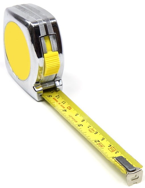
This measuring tool is one of the most popular items among all the measuring tools in the world. You will see this item everywhere. It is available not only in metalworking workshops but also in other manufacturing places.
A measuring tape is thin, and a long flexible ruler measures the objects’ length and sizes. There are two basic types of measuring tape: self-retracting metal tape and plastic flexible measuring tape.
The measuring limit in measuring tape is generally up to 100 m and even more. The graduation used here depends on the sizes of the measuring tape. Usually, it has a graduation up to 1/32 inches. The accuracy has three different levels. Class 1 is accurate to ±1.10 mm, class 2 is accurate to ±2.30 mm, class 3 is accurate to ±4.60 mm in every 10m length.
24. Thread Pitch Gauge
Screws and nuts are very common in mechanical joints. We must know how they fit inside each other. We should be familiar with the threading process before we jump into the machining. Well, in this case, the thread pitch gauge is very helpful to measure the pitch or lead of a screw thread.
The real instrument looks like a set of multiple metal plates. Each of them has separate standards. It works as a reference tool to determine the pitch of a thread on a screw or in a tapped hole.
25. Wiggler (Tool)
Wiggler is not a single instrument. It has different names based on different uses, such as wobbler, edge finder, center finder, and laser-centering device. A wiggler helps to accurately align a machine with the work.
26. Tachometer
When it comes to inspecting the rotational speed of your mill or lathe machine, the tachometer is the right measuring instrument to do that. You could use the laser tachometer for more safety during the inspection.
Conclusion
To describe completely all of the above measuring tools in workshops need a lot of space to read. We focused on the summary of each of them. And thus, we tried to provide the basic information for each of the items. All of the above-stated measuring tools are very familiar with metalworking.
We gathered all of this information from our real-life knowledge and some other places on the internet considering the experiences of the machinists. We hope this article could help you know more about measuring tools in the workshop. And this will help you know a better way to do the machining.
